Overview
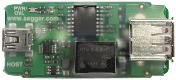
The USB Isolator can be interconnected between J-Link or Flasher and the host PC via USB, to provide electrical isolation of the J-Link or Flasher from the host (PC) side. This is essential when development tools are not connected to the same ground as the application. It is also useful to protect the development tools from electrical spikes, and overvoltage may occur when using low-budget USB hubs.
Key features
- Basic isolation (3 kV DC for 1s)
- Propagation delay 70 ns max. (to be treated as one additional hub)
- Max. output current 200 mA (meaning that the connected debug probe may not consume more than 200 mA)
- USB Full-Speed
- Short circuit protection
- 2 LEDs to indicate power and overload status
Connectors and indicators
The USB Isolator comes with the following connectors and indicators:
- USB type Micro-B connector on the host (PC) side
- USB type A connector on the Flasher side
- Green LED indicating that the USB Isolator is powered and can provide power to the Flasher side
- Red LED indicating that the power consumption of the debug setup (Isolator + Flasher) is too high. The max. current that may be drawn by the debug probe connected to the Isolator is is 200 mA.
How to use the USB Isolator with J-Link
Using the USB Isolator with J-Link is pretty simple: Just plug in the USB Isolator between the J-Link USB connector and the host PC. As soon as the PC-side of the USB Isolator is plugged in, the green PWR LED of the Isolator is lit. If the red/orange OVL LED is lit, power consumption of the debug probe is too high. The max. current that may be drawn by the debug probe is 200 mA.
Target-side isolation vs. host-side isolation
Host-side isolation forces the Host to set the USB Link to Full Speed (12 MBit) when connecting to J-Link or Flasher. This is typically fully sufficient and does not or not significantly reduce the debug and flash programming speed. With host-side isolation, both J-Link and the target are isolated from the host, whereas target-side isolation isolates the target from both Host and J-Link. This can be desirable in metering applications, as it introduces the least amount of noise from the debug probe to potentially sensitive ADC readings.
Host-side isolation works with all supported types of debug interfaces, JTAG, SWD (with or w/o SWO), FINE, C2, UART, ... Target-side isolation allows High-Speed USB connection (480 MBit) with all J-Link models supporting it, but typically limits the maximum speed on the debug interface (target side).
Target side isolation options for J-Links are:
How to use USB Isolators from other vendors with J-Link
The full J-Link and Flasher families are designed to work with the USB Isolator, but may also be used with USB Isolators from other vendors. However; this use is done outside of SEGGER support and done at your own risk!
Safety
This isolator provides basic isolation only. Do not use with hazardous voltages without further protection measures to avoid risk of electrical shock and fire.
SEGGER isolators provide a basic isolation to withstand high voltages as mentioned in the resp. technical data section. To preserve integrity of human beings when dealing with potential hazardous voltages it is mandatory to have a second protection measure in place in case the first insulation barrier fails. This is called double or reinforced isolation. How this double isolation can be achieved depends on the use case or application setup. Also check your local safety related directives valid for your country to make sure all requirements are met.


